Video Coding Walkthrough
This example shows how a video frame is encoded (compressed) and decoded (decompressed). The frame is processed using a simple motion compensated transform encoder, similar to an early MPEG codec. However the basic principles apply to more sophisticated codecs such as H.264, VP8, etc.
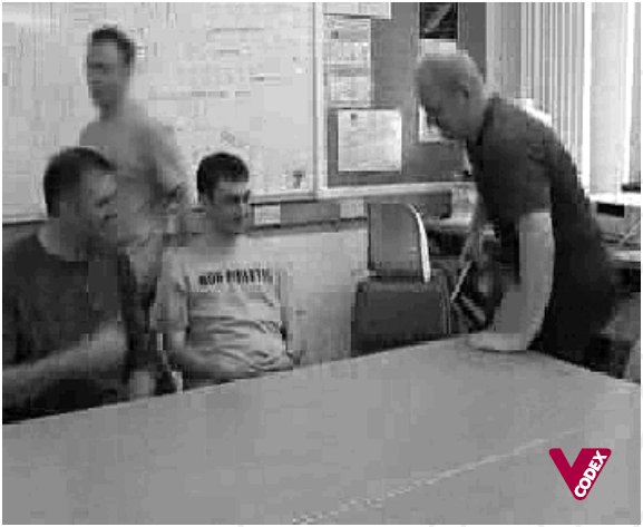
The original frame is taken from a CIF video sequence, which means that the luma or luminance component shown in Fig. 1 is 352 samples wide and 288 samples high. The red/blue chroma components, not shown, are each 176x144 samples.
Fig. 2 shows the reconstructed previous frame in the video sequence. This has been encoded and decoded (=reconstructed) and some distortion can be seen. The difference between Fig 1 and Fig 2 without motion compensation is shown in Fig. 3. There is clearly still significant energy in Fig. 3, especially around moving areas.
Fig 1 - Input frame Fig 2 - Reconstructed reference frame
Fig 3 - Residual: no motion compensation
Motion estimation is carried out with a 16x16 block size and half-pixel accuracy, producing the set of vectors shown in Fig. 4, superimposed on the current frame for clarity. Many of the vectors are zero and are shown as dots, which means that the best match for the macroblock is in the same position in the reference frame. Around moving areas, the vectors point in the direction that blocks have moved from. The man standing on the left of the picture is walking to the left; the vectors therefore point to the right, i.e. where he has come from. Some of the vectors do not appear to correspond to “real” movement, for example those on the surface of the table, but indicate simply that the best match is not at the same position in the reference frame. “Noisy” vectors like these often occur in regions of the picture where there are no clear object features in the reference frame.
Fig 4 - 16x16 motion vectors superimposed on frame
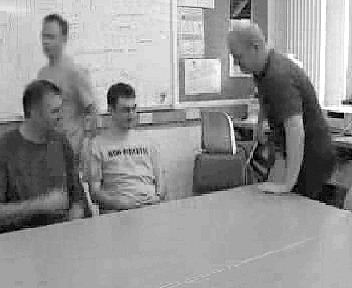
Fig. 5 shows the motion compensated reference frame, i.e. the reference frame with each block shifted according to the motion vectors. The walking person has been moved to the left to provide a better match for the same person in the current frame and the hand of the left-most person has been moved down to provide an improved match. Subtracting the motion compensated reference frame from the current frame gives the motion-compensated residual (Fig. 6). Compared with Fig. 3, the energy has clearly been reduced, particularly around moving areas.
Fig 5 - Motion compensated reference frame Fig 6 - Motion compensated residual frame
Fig. 7 shows a macroblock from the original frame, taken from around the head of the figure on the right. Fig. 8 is the luma component of the same macroblock after motion compensation. This is known as the residual.
Fig 7 - Original macroblock: luminance Fig 8 - Residual macroblock: luminance
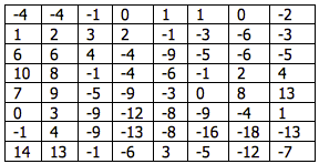
Each block within the residual macroblock is transformed using a Discrete Cosine Transform (DCT). Applying a two-dimensional DCT to the top-right 8x8 block of luminance samples (Table 1) produces the DCT coefficients listed in Table 2. The magnitude of each coefficient is shown in Fig. 9. Note that the larger coefficients are clustered around the top-left or DC coefficient.
Fig 9 - DCT coefficient magnitudes: top-right 8x8 block
Table 1 - Residual luminance samples : top-right 8x8 block Table 2 - DCT coefficients
A forward quantizer is applied:
Qcoeff = round(coeff/Qstep)
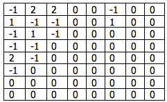
where Qstep is the quantizer step size, Qstep=12 in this example. The output of the quantizer is shown in Table 3. Small-valued coefficients become zero in the quantized block and the non-zero outputs are clustered around the top-left (DC) coefficient.
Table 3 - Quantized coefficients
The quantized block is re-ordered in a zigzag scan starting at the top-left to produce the following list of coefficients:
-1, 2, 1, -1, -1, 2, 0, -1, 1, -1, 2, -1, -1, 0, 0, -1, 0, 0, 0, -1, -1, 0, 0, 0, 0, 0, 1, 0,… (all zeros after this)
This array is processed to produce a series of (run, level) pairs:
(0, -1)(0,2)(0,1)(0,-1)(0,-1)(0,2)(1,-1)(0,1)(0,-1)(0,2)(0,-1)(0,-1)(2,-1)(3,-1)(0,-1)(5,1)(EOB)
The first number in each pair indicates the number of preceding zeros and the second number indicates the non-zero “level”. “EOB” (End Of Block) indicates that the remainder of the coefficients are zero.
Each (run, level) pair is encoded as a variable length code (VLC). Using the variable length code tables from MPEG-4 Visual, the VLCs shown in Table 4 are produced.
Table 4 - Variable length coding example
The final VLC signals that LAST=1, indicating that this is the end of the block. The motion vector for this macroblock is (0, 1), i.e. the vector points downwards. The motion vector X and Y components are (differentially) coded as (1) and (0010) respectively.
The macroblock is transmitted as a series of VLCs, including a macroblock header, coded motion vector and transform coefficients for each 8x8 block.
At the decoder, the VLC sequence is decoded to extract header parameters, coded motion vectors and (run,level) pairs for each block. The 64-element array of coefficients is reconstructed by inserting (run) zeros before every (level). The array is then ordered to produce an 8x8 block identical to Table 3. The quantized coefficients are rescaled using:
Rcoeff = Qstep.Qcoeff
Rescaling or inverse quantization produces the block of coefficients shown in Table 5. This block is significantly different from the original DCT coefficients (Table 2) due to the quantization process. An Inverse DCT is applied to create a decoded residual block (Table 6) which is similar but not identical to the original residual block (Table 1). Comparing the original and decoded residual blocks in Fig. 10, it is clear that the decoded block has less high-frequency variation because of the loss of high-frequency DCT coefficients through quantization.
Table 5 - Rescaled coefficients Table 6 - Decoded residual luminance samples
Fig 10 - Original and decoded residual blocks
The decoder recreates the original motion vector (0, 1). Using this vector, together with its own copy of the previously decoded frame (Fig. 2), the decoder reconstructs the macroblock. The complete decoded frame is shown in Fig. 11. Because of the quantization process, some distortion has been introduced, for example around detailed areas such as the faces and the writing on the board and there are some obvious edges along 8x8 block boundaries. The complete sequence was compressed by around 300 times, i.e. the coded sequence occupies less than 1/300 the size of the uncompressed video. Significant compression is achieved at the expense of relatively poor image quality.
Fig 11 - Decoded Frame
Further reading
Iain E. Richardson, “The H.264 Advanced Video Compression Standard”, John Wiley & Sons, 2010.
Iain E. Richardson, “Coding Video: A Practical Guide to HEVC and Beyond”, John Wiley & Sons, 2024.
About the author
Vcodex is led by Professor Iain Richardson, an internationally known expert on the MPEG and H.264 video compression standards. Based in Delft, The Netherlands, he frequently travels to the US and Europe.
Iain Richardson is an internationally recognised expert on video compression and digital video communications. He is the author of four other books about video coding which include two widely-cited books on the H.264 Advanced Video Coding standard. For over thirty years, he has carried out research in the field of video compression and video communications, as a Professor at the Robert Gordon University in Aberdeen, Scotland and as an independent consultant with his own company, Vcodex. He advises companies on video compression technology and is sought after as an expert witness in litigation cases involving video coding.